
3.2.4 Edit

When clicking the "Top Toolbar - Edit" button, the "Edit" function bar will automatically pop up on the left side. Edit mainly includes nine sub-functions: "Model Repair", "Hollow", "Label", "Scan Fill", "Drill", "Model Link", "Custom Cut", "Gingiva Shell", and "Z-Compensation".
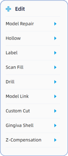
- Model Repair: Mainly used to fill data holes and support automatic reconstruction for models with issues caused during scanning or export from design software.
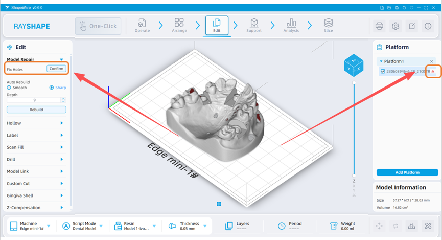
1) Fix Holes is primarily used for data holes and missing meshes, which commonly occur in applications such as dental models. Upon model import, the software will automatically detect holes and prompt the user. At this point, users can click the "Edit - Model Repair - Fix Holes" button on the left panel to repair them, or click the warning icon under "File List - Platform - File Status" on the right panel to execute the repair (Auto Rebuild + Fix Holes).
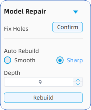
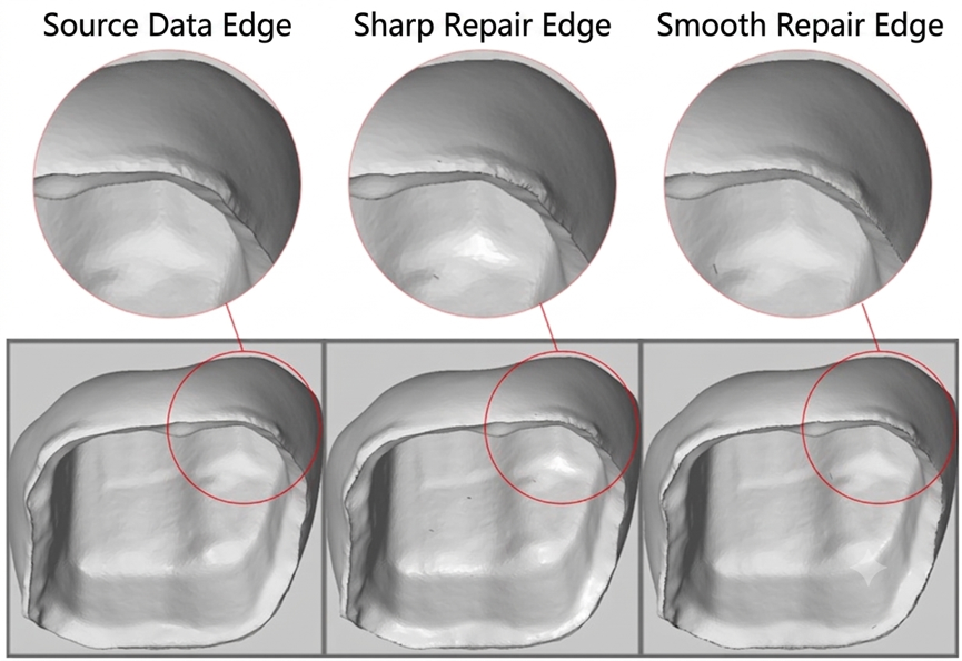
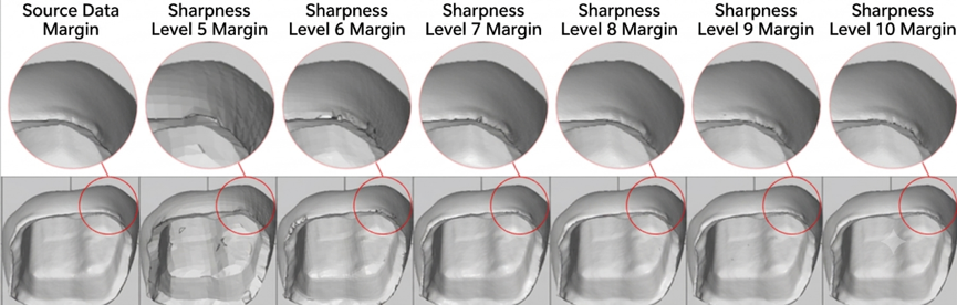
2) Auto Rebuild is primarily used for cases involving duplicate meshes and redundant intersections, which commonly occur in applications such as temporary crowns or immediate loading. Upon model import, the software will also automatically detect mesh intersections and prompt the user. At this point, users can click the "Edit - Model Repair - Auto Rebuild" button on the left panel to execute reconstruction, or click the warning icon under "File List - Platform - File Status" on the right panel to perform the repair (Auto Rebuild + Fix Holes). The mode options in Auto Rebuild—Smooth and Sharp—represent the smoothness of the model file edges after repair. To achieve the highest detail accuracy, the "Sharp" option is recommended. The Depth selection in Auto Rebuild (levels 1-10) represents the detail precision of the model file edges after repair; a higher depth results in higher repair fidelity, but requires greater computer computing power and longer repair time, so level "9" is recommended. In addition, users must strictly control the quality of intraoral scan data or design data. With bad date quality there is a very high probability that an error will be reported or the slicing process will be terminated in subsequent stages. Any print failures or quality issues caused by neglecting data repair shall be borne by the user.
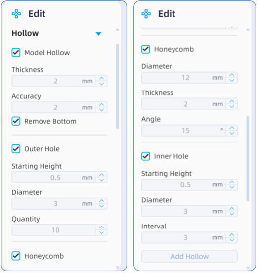
- Hollow: Mainly includes functions such as model shelling (bottom removal), side drain holes, honeycomb structures, and internal drain holes.
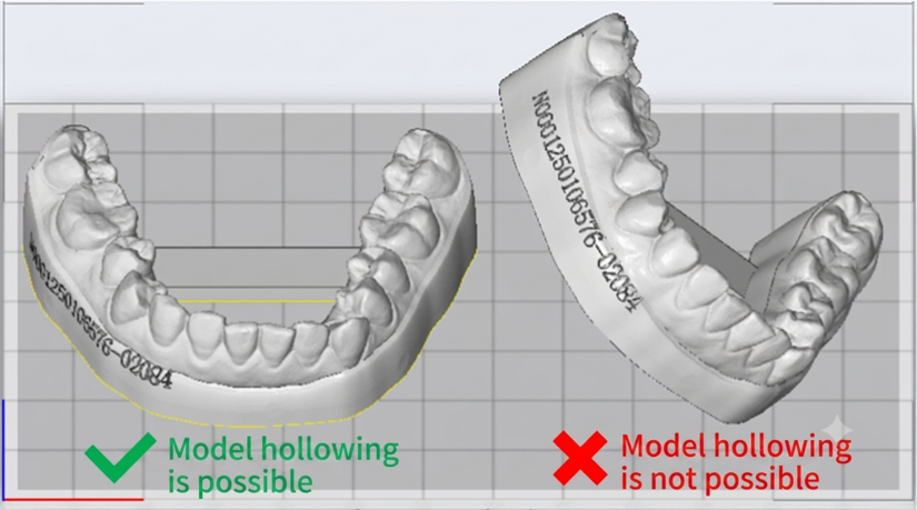
1)Models that require the Hollow operation must undergo the Auto Placement operation in advance to ensure that the model is flush against the platform bottom.
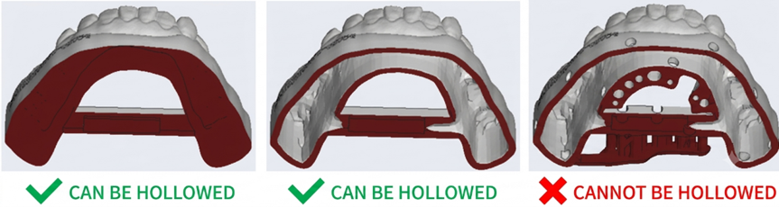
2) Models that require the Hollow operation must either be completely solid without being shelled, or be in a shelled state without any drain holes added. If the user has pre-shelled the model and added drain holes in the design software—causing the interior and exterior of the model to form a "continuous" conjugate surface—it will cause the software to misjudge the geometry and fail to execute any further Hollow operations, which may even lead to the software freezing or reporting an error directly.
3) Model Shelling: When this option is checked and the "Add Hollow" button is clicked, the software will perform internal hollowing on the model. If the "Remove Bottom" option is additionally checked, the software will first remove the bottom surface and then hollow the model. Please note that when the "Remove Bottom" option is unchecked, the "Honeycomb Structure" function will be deactivated, meaning a honeycomb structure cannot be added inside a completely enclosed cavity. The shelling thickness represents the reserved wall thickness for hollowing, with a default value of 2 mm (to ensure the precision retention and deformation resistance of the printed model, it is recommended to set this value to 2-2.5 mm); Accuracy represents the internal mesh resolution, with a default value of 2 mm; the larger the value, the rougher the internal structure will be.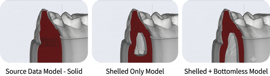
4) Side Drain Holes: When a model requires the Hollow operation, theoretically, side drain holes should be added regardless of whether the bottom is removed; otherwise, supports must be added. If a model is shelled without side drain holes or supports, a closed internal cavity will be formed. This not only traps the resin material and prevents it from draining, but also compromises the surface quality of the printed model. Therefore, after checking the "Model Shelling" option, users should directly check the "Side Drain Holes" option. In the parameter settings for side drain holes, the starting height represents the vertical height of the hole position relative to the bottom surface of the model; the hole diameter represents the size of the drain hole's diameter; and the hole quantity represents the total number of drain holes distributed along the projected contour path of the model's outer perimeter.
5) Honeycomb Structure: To ensure the structural stability and deformation resistance of the printed model, it is recommended to directly check the "Honeycomb Structure" option during model shelling. This creates regular grids inside the model that extend downward from the inner wall to support the internal shelled structure. Among the configurable parameters, the honeycomb diameter represents the diameter of the inscribed circle of the hexagonal honeycomb structure; the border thickness refers to the distance between adjacent hexagons, which is the wall thickness of the grid; and the support angle relates to the automated shelling process, where downward-protruding structures on the inner wall form isolated islands (hereinafter referred to as "overhang points"). To ensure successful printing of these islands, the honeycomb structure grids must transition and merge with the overhang points to provide "internal supports." The support angle here refers to the transition angle between this "internal support" and the overhang point, with a default value of 15°.
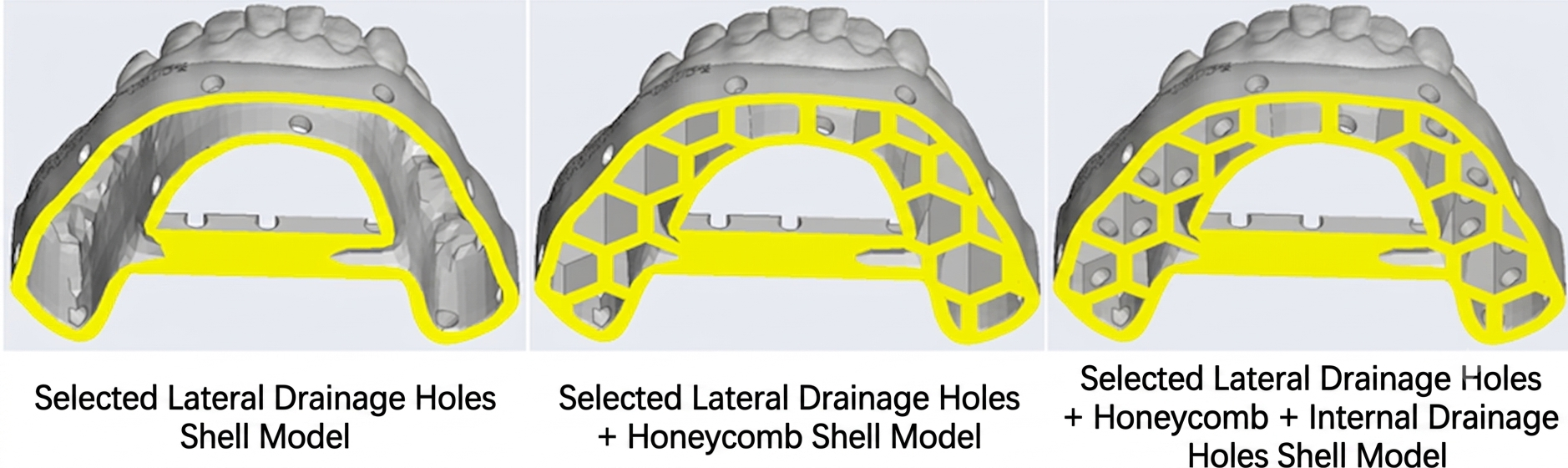
6) Internal Drain Holes: As mentioned previously, if a model undergoes shelling and grid generation, individual isolated cavities will still form inside the grid even if side drain holes are added. This creates a "cupping effect" during the printing process, trapping the resin and leading to rough internal and external surfaces. Therefore, when checking the "Side Drain Holes" and "Honeycomb Structure" options, it is highly recommended to check the "Internal Drain Holes" option simultaneously.
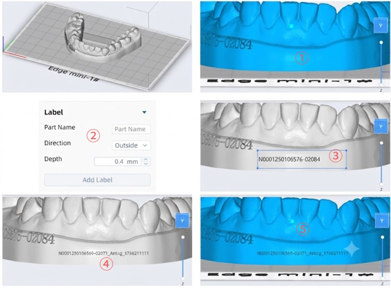
- Label: Primarily designed for scenarios where users need to manually add text labels onto the model surface. Users can perform the following operations:
① Double-click the left mouse button on the surface of the model where the label is to be added, and the camera viewpoint will automatically lock and focus on that area.
② Click the "Add Label" button and enter the text content (the default text is the name of the imported model file). Select "Emboss" or "Engrave" for the text mode, and define the height or depth of the embossment/engraving via the text depth parameter.
③ Click and hold the left mouse button at the upper-left point of the designated position, drag it toward the lower-right corner until the entire bounding box is drawn. The size of the label text will automatically scale to fit within this bounding box.
④ Click the "√" button to confirm the current label placement. If the position needs to be redefined, click the "×" button and repeat step
⑤ Click the "Exit Edit" button to complete the labeling operation. The text will automatically project and conform onto the model surface according to its contour variations.
- Scan Fill: Primarily designed for scenarios where intraoral scan (IOS) data can be directly closed and printed without undergoing extensive CAD design. Please note:
1) The IOS data must be as accurate and complete as possible, without excessive redundant "flashes" or flying meshes. This requires a thorough and complete scan of key clinical areas during the intraoral scanning process to avoid any visible holes, especially in the restoration area. After scanning, corresponding cropping and removal operations should be performed within the scanning software to clear away redundant meshes.
2) IOS data consists of non-closed independent meshes rather than a fully sealed solid structure, which means the 3D printer cannot directly recognize it. Upon file import, the software will immediately detect the non-closed state and prompt the user to repair and fill it. In this case, do not directly execute the "Edit - Model Repair - Fix Holes" operation, as its closure effect is insufficient; for IOS data, the "Scan Fill" operation must be used instead.
3) The bottom-capping process is essentially a projected "drafting" mechanism. The fewer the redundant meshes on the edge, the cleaner and more regular the surface perimeter of the closed data will be.
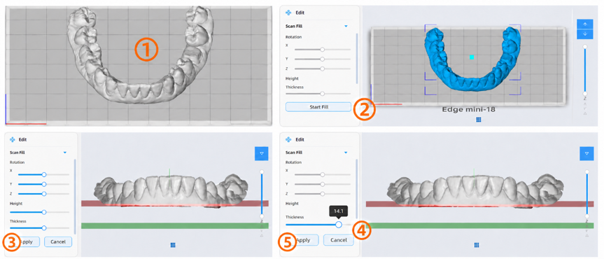
To perform IOS data closure, users can proceed with the following steps:
① Orient the IOS data correctly in advance, ensuring that its occlusal plane is as parallel to the print platform surface as possible.
② Click to select the model to be closed, and then click the "Start Fill" button.
③ Slide the height gauge left or right to adjust the portion of the IOS data to be retained (the area above the red cross-section) according to your needs. It is recommended to reserve the area below the gingival margin, or even down to the frenum.
④ Slide the thickness gauge left or right to adjust the base height of the IOS data. A base that is too thick will waste printing material, while one that is too thin will reduce the model's resistance to deformation; therefore, a base height of no less than 10 mm is recommended.
⑤ Click the Apply button to complete the IOS data closure. If the model requires further trimming or sectioning after closure, you can execute the "Edit - Custom Cut" operation.
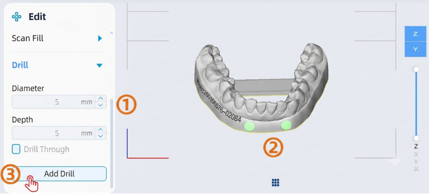
- Drill: Primarily designed for scenarios where users need to manually create blind holes or through holes on the model. Users can perform the following operations:
① Enter the required hole diameter and hole depth. If the hole needs to pierce completely through the model, check the corresponding through-hole option.
② Select the model and single-click the left mouse button on the desired position to place a hole. Users can rotate the model to adjust the viewpoint and click each location where a hole is needed one by one.
③ Click the Apply button to complete the drilling operation. If you need to adjust or modify the hole positions before applying, click the Cancel button and repeat steps ① and ②.
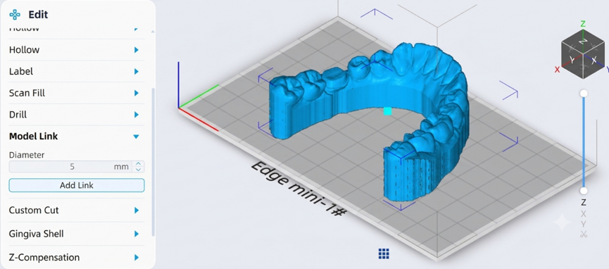
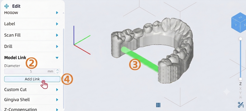
Model Link: Primarily designed for scenarios where users need to manually add connecting bars to enhance the model's resistance to deformation. Users can perform the following operations:
① Select the model and click the "Add Bar" button.
② Enter the diameter value for the connecting bar. It is recommended that this value be no less than 5 mm.
③ Click on the model in sequence to select the starting point and ending point of the connecting bar.
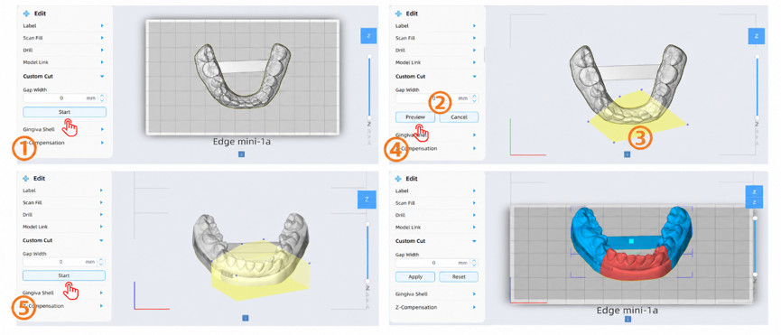
Custom Cut: Primarily designed for scenarios where users need to section a model or trim off certain parts. Please note:
1) Intraoral scan (IOS) data must be fully closed via the "Scan Fill" operation before the Custom Cut operation can be performed.
2) Models must be processed one by one.
To perform a custom cut, users can proceed with the following steps:
① Select the model and click the "Start Add" button.
② Enter the cutting gap. This value represents the offset distance between the two partitioned sides after sectioning, with a default value of 0 mm.
③ Single-click the left mouse button point by point to draw and define the cutting path.
④ Click the "Preview" button to rotate or switch viewpoints to verify the accuracy of the cut.
⑤ Click the "Confirm" button to complete the custom cut operation. Note: When the cutting gap is set to 0 mm, the two separated models will remain infinitely close to each other. The software will detect this as an overlapping "interference/collision" state and highlight them in red.
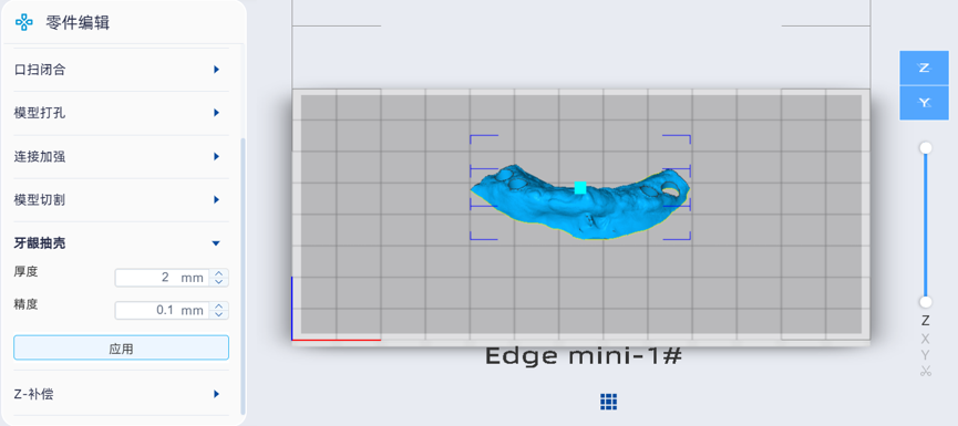
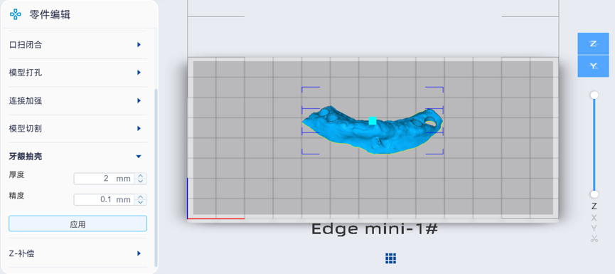
Gingiva moldingl: Primarily designed for scenarios where gingival design data undergoes reverse shelling to create a mold, facilitating the injection or casting of gingival mask materials. Please note:
1) The gingiva data must undergo data repair before shelling to ensure it is complete, manifold (closed), and of good quality.
To perform a gingiva shell operation, users can proceed with the following steps:
① Select the model, then enter the thickness and accuracy values. Thickness refers to the wall thickness of the mold shell. Accuracy refers to the mesh resolution of the shell after the operation, with a default value of 0.1 mm. The smaller this parameter value, the finer the mold details will be, but the longer the computation time required; conversely, a larger value results in rougher details.
② Click the "Apply" button to complete the gingiva shell operation.
- Z-Compensation: Primarily designed for scenarios where dimensional value compensation is required due to resin over-cure issues. Users must perform compensation operations under the guidance of technical support or technical understanding.